The Motorola Radius SM50 is an old business band radio that has been converted by many to serve as repeaters. There is plenty of documentation over on Repeater Builder about this radio including service manuals. I decided to pick one of these up to use with APRS. Specifically I planned on setting it up with a weather station.
There are a few different varieties of these radios, some are 2 channels models while others are 16 channel. Another difference is the power output. These radios come in 25 and 40 watt versions. The Repeater Builder website has a great breakdown of the model numbers and which features go with which. For APRS, you'll primarily be looking for one of these models:
| Model Number | Model | Band | Power out | |||
| M33DGC20A2AA | SM50 | VHF | 25 Watts | |||
| M43DGC20A2AA | SM50 | VHF | 40 Watts | |||
| M33DGC20C2AA | SM120 | VHF | 25 Watts | |||
| M43DGC20C2AA | SM120 | VHF | 40 Watts |
I was able to find a M43DGC20A2AA which is a 2 channel 40 watt version on e-bay for about $35. Now that I had a radio, I needed to get it programmed for the 2m ham band. While not a difficult step, it's also not an easy step. The software for these radios is DOS based. Additionally the software is not that easy to find, but a little searching on Google will get you what you're looking for. I followed the directions available here with great success. I'm going to document my process for the purpose of duplication incase the other site goes away.
Programming Process
Software
As I mentioned above, you'll need a DOS program from Motorola to program this radio. You'll also need to run DOS Box in order to run the SM50 programming software. The software can be found on Google by searching for SM50 RSS. I ran the software in DOS Box on Windows, but you can also run it on Linux if you choose. The software version you will need to download is SM50/SM120 R04.00.00 RSS.
Terminology
Motorola likes to make things slightly more difficult by calling things by different names. The first being RSS, which is simply the software for programming Motorola radios. Net up is the RIB, which is what they call their programming cables.
Originally these used to be a box that you would plug into the radio and then into a computer. This is where the name Radio Interface Box comes from. The next bit of Motorola jargon is the code plug. This is nothing more than the configuration data for the radio.
Programming Cable
As mentioned earlier, a programming cable can either be purchased from e-bay, or if you're homebrew inclined, you can easily make one. The programming cable works off of a single line serial bus which we'll need to convert to two line. A schematic is available from George Smart M1GEO's that works quite well. To make your own programming cable, you'll need the following items:
- USB to TTL UART. These can be had on e-bay for $1-4.
- A switching diode such as a 1N4148. These can also be found on e-bay for $2 for about 20.
- An ethernet cable, we'll only need two wires out of the eight.
I used a bread board to set my cable up, but you could also solder the wires and diode to the pins of the UART. The wiring is simple as seen in M1GEO's schematic. Connect the blue/white wire to the ground pin, and the orange wire to the RX pin. You'll then need to bridge the TX and RX pins with the diode. The part of the diode with the line, the cathode, will need to be on the TX side while the anode will be on the RX side.
Downloading the RSS
Once you download the software, it will be packaged in a zip file. Unzip this file to whatever directory you choose. Inside this folder with be a file named SM50.EXE, this is the programming software. Next you need to plug your USB UART in and determine which COM port it is assigned. You can find the COM port under Device Manager > Ports (COM & LPT).
DOSBox
To run the RSS, you'll need to download DOSBox. You can download it from here. After downloading, go ahead and run the installer.
After DOSBox has been installed, you'll need to run it momentarily so that a config file can be created. Once you've started the program, you can close it. Browse to the install directory and open DOSBox 0.74-3 Options.bat. The file name may vary slightly depending on the version you have installed at the time.
Once you have opened the file, you will need to find two sections and make some changes. The first section is [serial] and it will be towards the bottom. Edit this section as follows:
[serial]
serial1=directserial realport:comX
Replace comX with the com port number you found in the Device Manager.
The next section you'll want to change is [autoexec]. This is where you'll mount folders from the host machine.
[autoexec]
# Lines in this section will be run at startup.
# You can put your MOUNT lines here.

mount c [file path to SM50]
C:
Enter the file path of where you have the SM50 RSS extracted.
Installing SM50 RSS
Start up DOSBox once again and run SM50.exe at the prompt.
Enter "Y" for all of the prompts during install. Once the installation is complete, you can now run the SM50 program by typing SM50 at the prompt.
Reading from the Radio
Now it's time for the magic to happen. If you've assembled your cable correctly and have DOSBox properly set up, then now is the time to read the codeplug from your radio.
If you haven't already, enter SM50 at the prompt to start the RSS. Press "Any Key" to continue to the main menu.
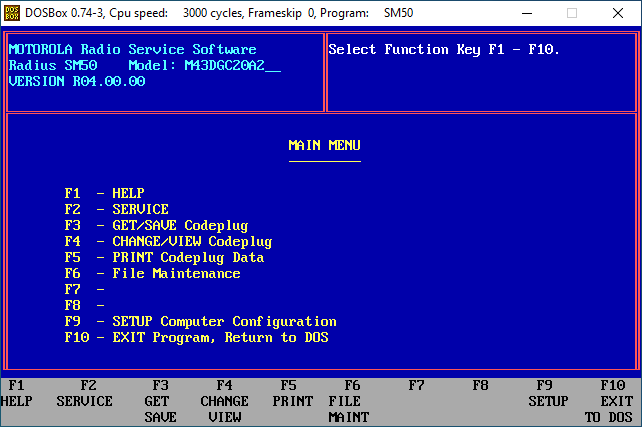
Being an old DOS program there is no mouse control. Everything is done with the Function keys, tab and the arrow keys.
GET/SAVE Codeplug
Before we can read from the radio, ensure that the program is running and the cable is connected. Then turn on the radio, otherwise the RSS may not read from the radio.
Before we program our radio, we need to read the current codeplug and save it as a backup. To do this, from the main menu, press F3 - GET/SAVE Codeplug.
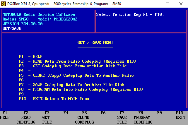
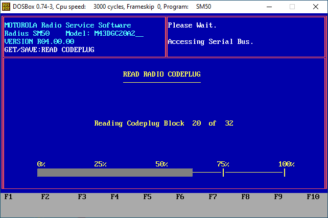
In the GET/SAVE Codeplug menu, next press F2 - READ Data From Radio Codeplug. This will read the current codeplug from the radio. You should see a progress bar while the codeplug is being read from the radio. Once everything is done, the radio will beep to let you know it is leaving programming mode. Your radio model will be displayed at the top left of the screen.
Save the Codeplug
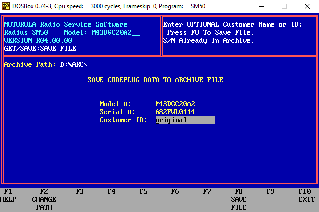
Next we will save the codeplug that is on the radio so that we have a backup. This step is optional, but it never hurts to have the original codeplug that your radio came with. From the GET/SAVE menu, press F7 - SAVE Codeplug Data To Archive File Disk. Change the file path to C:\ARC (or whatever drive letter you assigned the mount to) and press enter. Optionally enter something useful into the Customer ID box to help remember what the codeplug is in the future. Press F8 to save the codeplug to file and then press F10 twice to exit back to the main menu.
View Current Configuration
Next we want to view the current configuration of the radio. To do this, we will press F4 - CHANGE/VIEW Codeplug. Next press F2 - RADIO WIDE Configuration. This screen will provide us with details about the radio based on it's model number such as output power, frequency, serial number etc. You'll notice that unless your radio has already been modified, it will show a frequency range of 150.0 - 170.0 MHz. Since this is outside of the amateur 2m band, we'll have to change it. To do so, we'll have to modify the RSS configuration file.
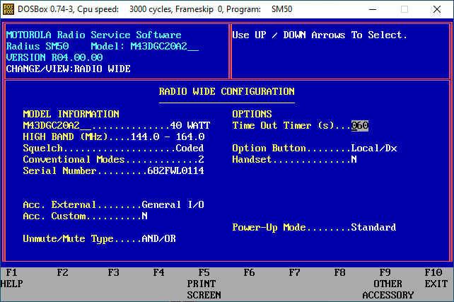
Exit the RSS by pressing F10 until you're returned to the DOS prompt.
Modifying the RSS Configuration
There are a lot of directions out on the internet on what needs to be changed in the configuration file so that we can use this radio on the 2m band. A much easier method however is to use a python script written by Mobilinkd. This script will modify the configuration file and make sure everything works properly. The file can be downloaded from here, or here. You will need Python installed on your computer, which is outside the scope of this tutorial.
Once you have downloaded the python script, place it in the SF50 folder. From here you will need to goto the Windows command prompt (Not DOSBox). Run the script by typing python mdfham2m.py SM50.MDF at the command prompt. This will then update the file to allow the use of the 2m band. A new file will be created, unfortunately the script doesn't properly make a backup and rename the new file under Windows. This is simple enough to do on our own though by renaming the SM50.MDF to SM50.MDF.Bak. The temp file will be something like tmpzmzp with some numbers. Rename this file to SM50.MDF.
Applying New Configuration to the Radio
Now that the RSS program has successfully been modified, we can go back into DOSBox and run SF50.
The programming software will start and once again press any key to get to the main menu. We will have to read the radios current codeplug in order to change it and write it back. The process to do so is as follows.
- Press
F3 - GET/SAVE Codeplug - Press
F2 - READ Data From Radio Codeplug - Press
F10 - EXIT/Return to Main Menu - Press
F4 - CHANGE/VIEW Codeplug - Press
F2 - RADIO WIDE Configuration
Now instead of 150.0 - 170.0 MHz, the radio should have a frequency range of 144.0 - 164.0 MHz.
Accessory Port Configuration
If you'd like to use the accessory port on the rear of the radio, then you will need to make some configuration changes. To access the accessory port you will need to view the Radio Wide Configuration screen.
- Press
F3 - GET/SAVE Codeplug - Press
F2 - READ Data From Radio Codeplug - Press
F10 - EXIT/Return to Main Menu - Press
F4 - CHANGE/VIEW Codeplug - Press
F2 - RADIO WIDE Configuration - Press
F7 - OTHER ACCESSORY
From here make the following changes:
Set Acc. RX Audio to Unmuted
Set Current Limiter to Post
Set pin 9 to External PTT
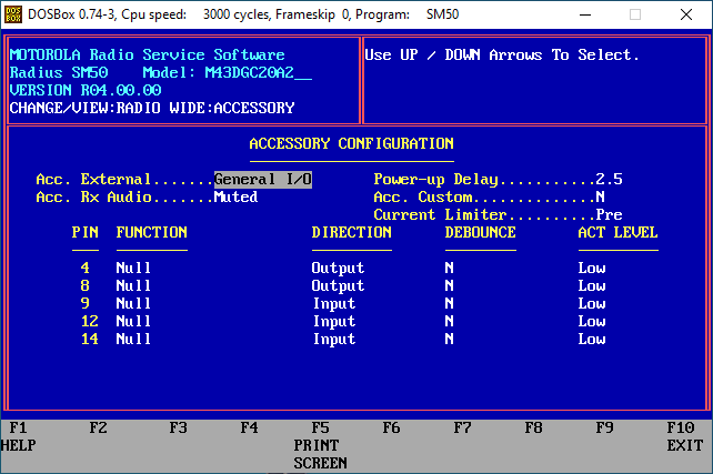
When you're done, press F10 to exit the screen.
Channel / Mode Configuration
Now we can go into the codeplug and program our desired frequency. Motorola calls the channels Modes. The 2 channel versions will have Mode 01, and Mode 02. From the main menu, press F5 - MODE Configuration. In my case I'm planning to use this radio for APRS, so I'll program both modes to the APRS frequency of 144.390 MHz. One mode will be full power, while the second mode will be programmed to a lower power of 5 watts.
Use the tab key and arrow keys to move between the fields and make the following changes:
RX Frequency ........... 144.39000TX Frequency ........... 144.39000Rx Squelch Type ....... CSQ
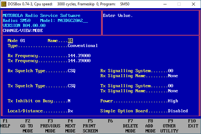
Press F4 to change to the next mode and make the following changes:
RX Frequency ........... 144.39000TX Frequency ........... 144.39000Rx Squelch Type ....... CSQ
Power ...................... Low
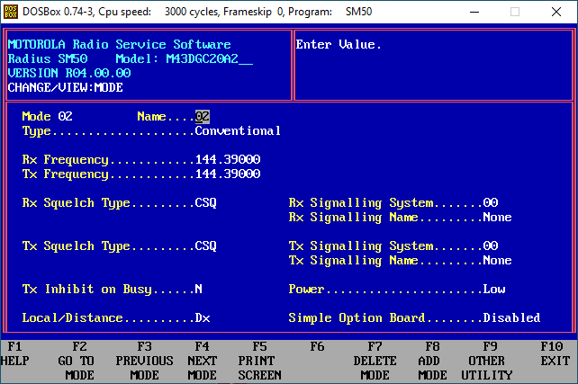
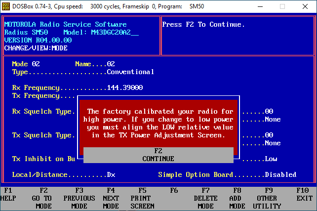
You will get a warning about the power being set at the factory and that changes will need to be made. We will get into this after we're finished with the codeplug. Press F10 twice to get back to the main menu.
Now we need to write the codeplug to the radio. From the main menu, perform the following:
- Press
F3 - GET/SAVE Codeplug - Press
F8 - PROGRAM Data Into Radio Codeplug - Press
F2 - Continue
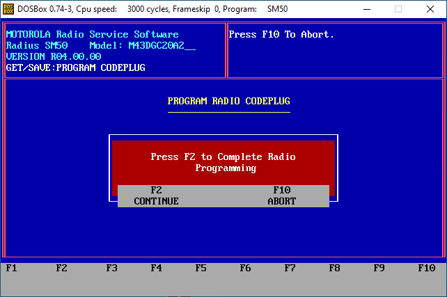
The software will now program the radio with the frequencies that you entered into the codeplug. Press F10 until you return to the main menu. If you did not program a low power mode, then you're done and you can exit the software. If you did program a low power mode, then continue onto the next step.
Adjusting Transmit Power
If you set one of your modes to use low power, then you will need to perform an alignment to set how many watts low power is. This is all done within the RSS software. Before performing these steps, you will need either an antenna, or a dummy load connected to the radio as it will key the transmitter.
From the main menu, press the following:
- Press F2 - SERVICE
- Press F2 - CONTINUE again if you have not programmed the radio with the current codeplug
- Press F2 - ALIGNMENT: Transmitter and Receiver
- Press F7 - TX POWER Coarse Adjustment
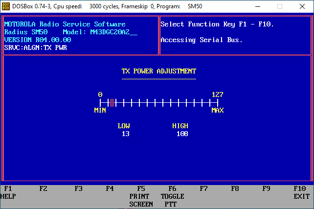
The software will then connect to the radio and you will see the TX POWER ADJUSTMENT window. There will be a LOW and HIGH. These are relative to the output power of the radio. The high number should equate to the output power of the radio, either 25 or 40 watts. In my case, I have a 40 watt radio and HIGH has a value of 108. In order to get a value for LOW, we will need to interpolate this number.
I used the linear interpolator on johndcook.com. To interpolate our low power, we will need 5 values. The bottom of the scale which is 0 watts, is 0. These will be our first two numbers. The top of the scale in my case for 40 watts is 108. These will be our second two numbers. Since I want my low power to be 5 watts, that will be my final number. Enter your numbers, 0, 0, 5, 40 and 108 into the calculator and click calculate. This will fill in the blank value with the number we need to enter in LOW. In my case for 5 watts, I need to enter 13.5. I just used 13 which will give me a hair under 5 watts, you could enter 14 if you wanted and get a hair over 5 watts.
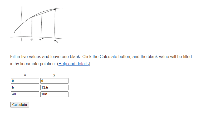
After you have entered the interpolated value on the TX POWER ADJUSTMENT screen, press F6 TOGGLE PTT. Ensure you radio is connected to an antenna or a dummy load first or damage could occur!
You should now have a LOW power set into the radio. Press F10 to exit back through to the main menu and to exit the software.
Conclusion
At this point your radio is now useable for APRS. You can use the front MIC port, or if you configured the accessory port you can use that as well. The accessory port can be used to connect a TNC to or a cable to use it as a repeater. At this point I won't be going into that as it's beyond my use case for the radio.
